 NOTE: Always unplug the Light-O-Rama board before opening the case or installing the wireless adapter as dangerous voltages are present!
These instructions are for the WiFi Adapter For Light-O-Rama CTB16PC Controllers. If you purchased one of the WiFi Adapter For Light-O-Rama CTB16PCG3 Controllers please refer to the instructions on How to Set up your CTB16PCG3 Wireless Adapter.
The setup for your new Wireless adapter is fairly straightforward. You will need a computer, tablet, or other WIFI device to connect to the board for the first time and configure it to connect to your wireless network. We suggest running your show on a separate wireless network from your home network in order to reduce traffic. The basic steps are as follows:
- Unplug the CTB16PC controller
- Attach the CTB16PC WiFi Adapter to the 18-pin header on the Light-O-Rama board and connect the Ethernet patch cable from the CTB16PC WiFi Adapter to the Light-O-Rama board
- Plug in the Light-O-Rama controller
- Connect wirelessly to the CTB16PC WiFi Adapter and configure for your network
- Enjoy blinky lights
The WiFi adapter has been designed to easily connect to the 18-pin header located at the top right of the LOR CTB16PC Board shown below and will allow you to still daisy chain multiple controllers. If you do not have the header in this location, check to the left for a 20-pin header. If this is present then you have the CTB16PCG3 board and will need to purchase the WiFi Adapter For Light-O-Rama CTB16PCG3 Controllers board instead.
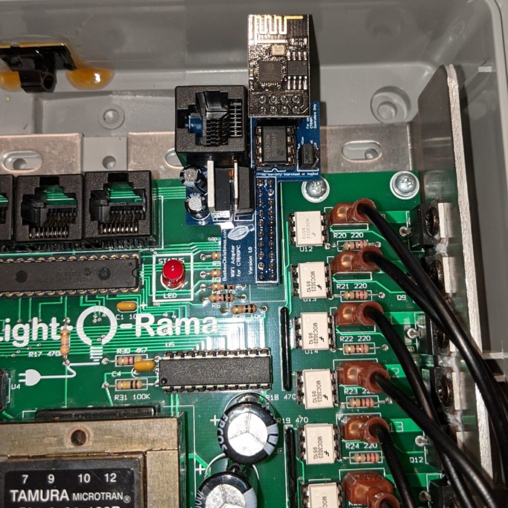
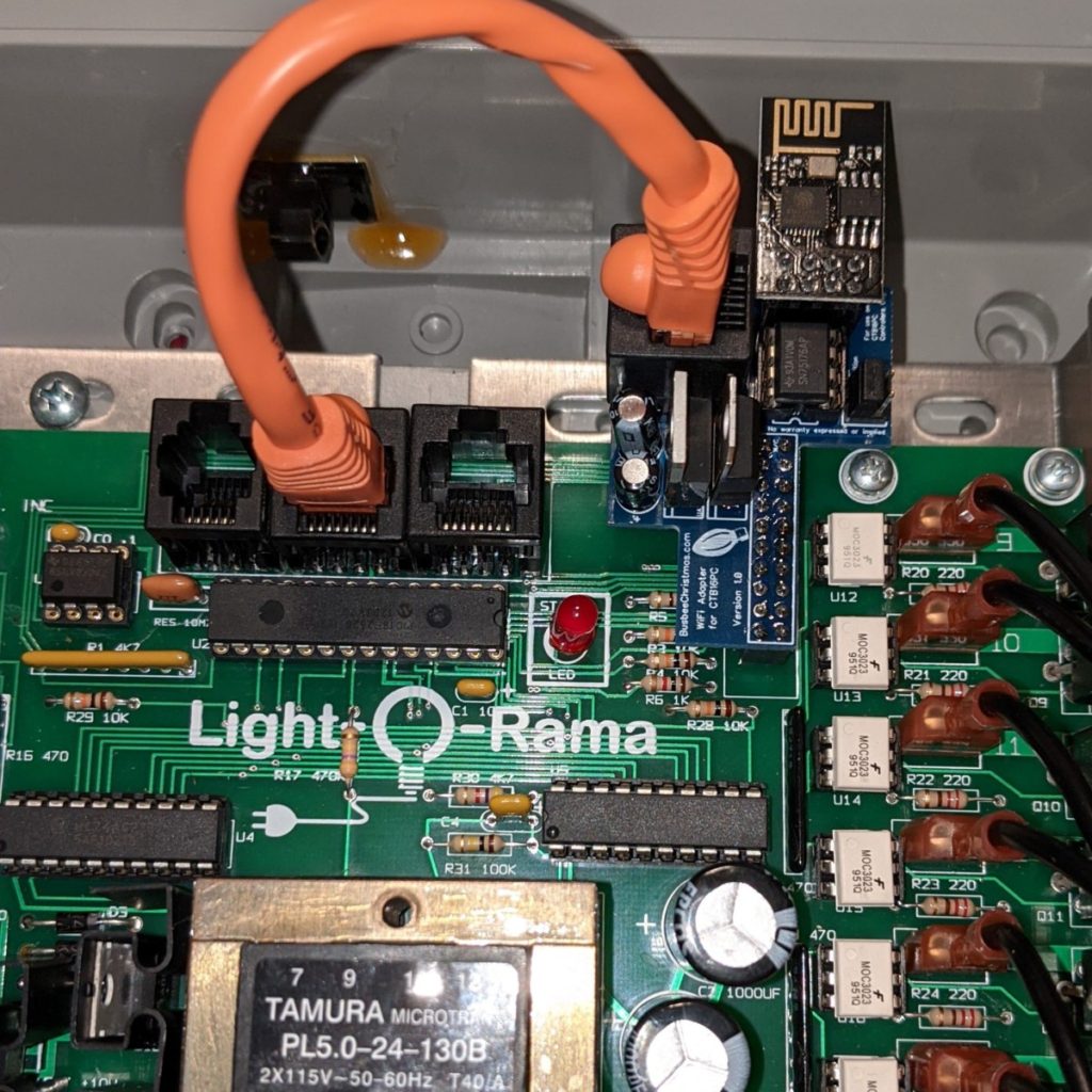
Check that the Light-O-Rama board is unplugged and place the new CTB16PC WiFi Adapter on the header as shown. Plug the ethernet patch cable from the adapter to the middle connector on the Light-O-Rama board.
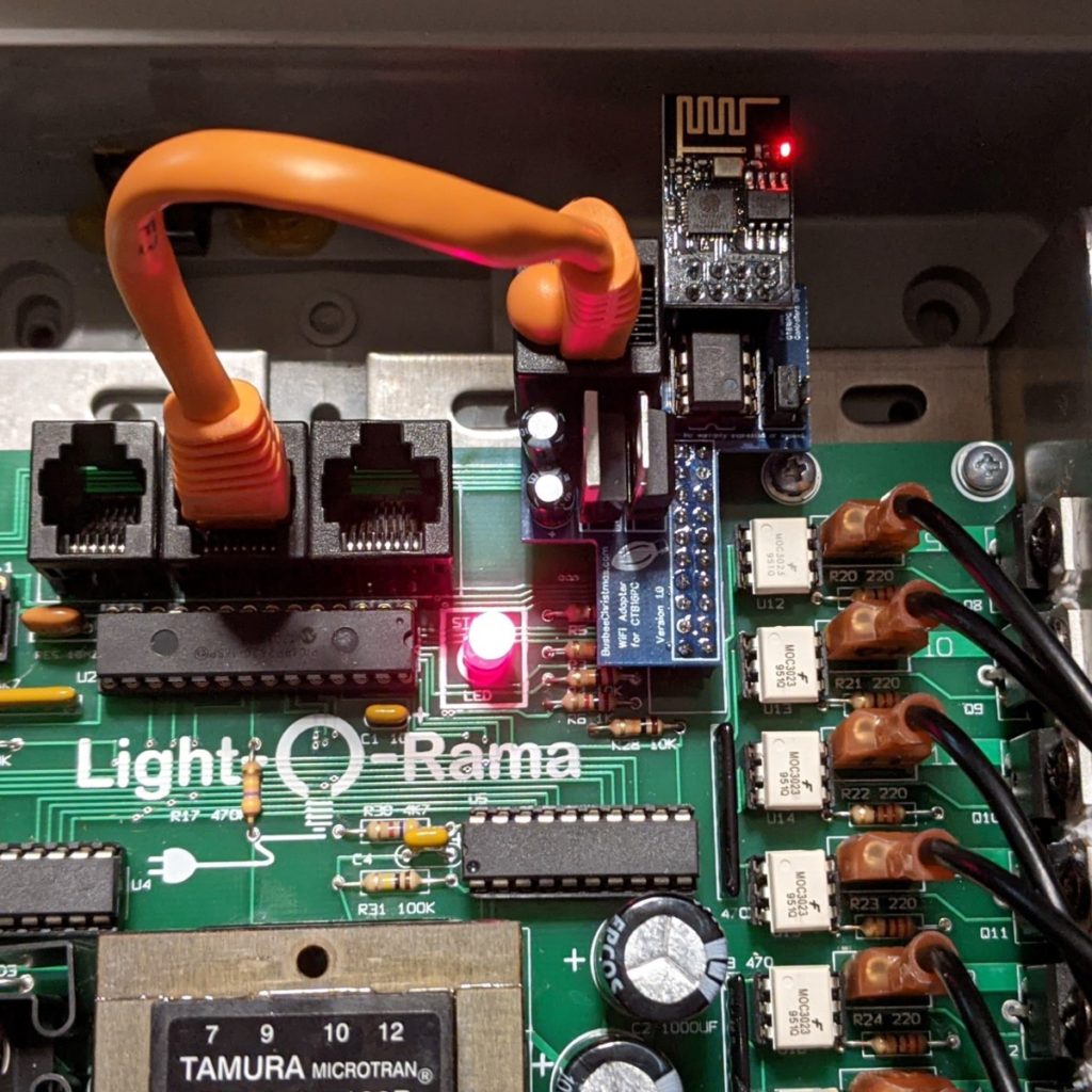
Plug in the board and watch to confirm that the correct lights show on the CTB16PC WiFi Adapter and the Light-O-Rama controller. After about 30-seconds the red LED on the Light-O-Rama board should turn solid, and the red LED on the CTB16PC WiFi Adapter will stay solid red. If the red LED on the Light-O-Rama board continues to blink, be sure the patch cable is plugged in securely.
Once the light is solid re, and you see the power indicator on the WIFI adapter (red led), close the cover and open your computer to browse for the WIFI connection.
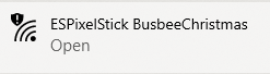
We now need to connect to the CTB16PC WiFi Adapter to set it up on your network. In your device of choice, open your WIFI connections and search for a new open network that begins with “ESPixelStick…” Connect to that network and open a web browser. You may get a notification that there is no internet connection present, so just disregard.
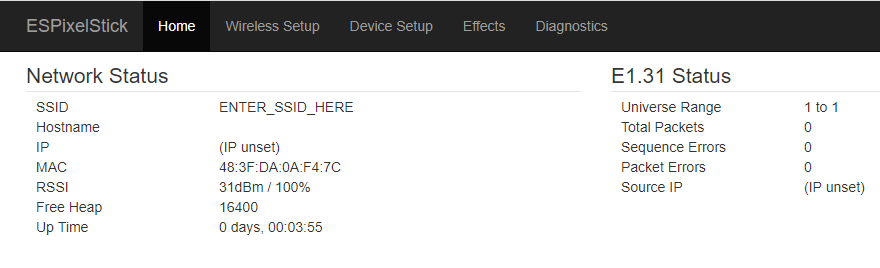
Navigate in your browser to 192.168.4.1 to get to the main menu on the CTB16PC WiFi Adapter. This will give you general information about the board based on the ESPixelStick firmware.
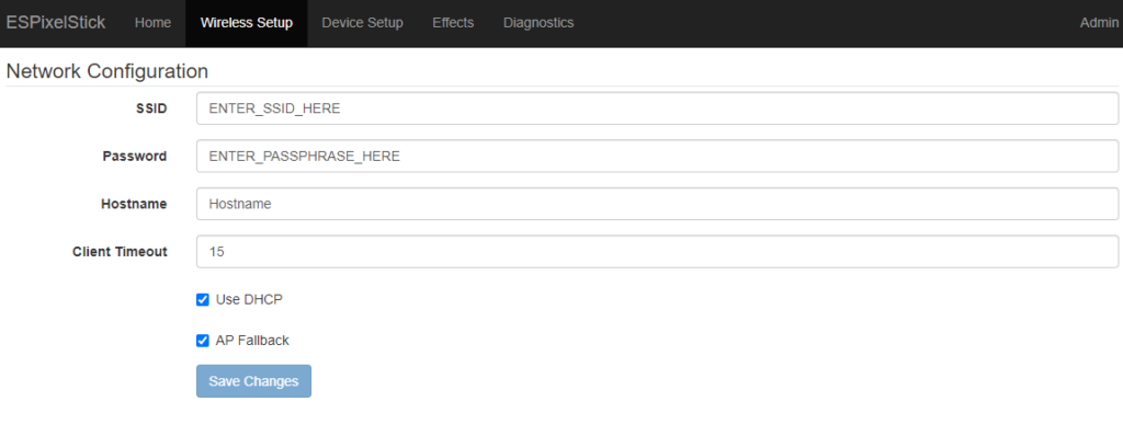
Click on “Wireless Setup” to enter the WiFi settings for your wireless network. Case is important, so be sure the SSID and Password cases match.
- Enter your WiFi SSID (Case sensitive)
- Enter your WiFi password
- Give a hostname so you can easily identify it on your network
- Leave DHCP to let your router assign an IP or uncheck to enter your own IP information
- Leave AP Fallback checked until you confirm that you can get on your WiFi network. Once you go live, you will want to uncheck this. While it is checked you can always connect to the device as shown above.
Click “Save Changes” to save the new configurations
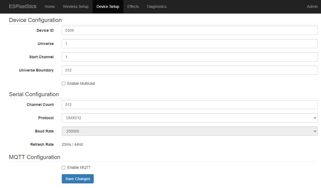
Once the new settings take effect, browse to the new IP that you gave in the last step, or go to your router to see the assigned IP. Put that in the address bar and then select “Device Setup” You will see that the default setting is for Universe 1 with 512 channels. You can change the Universe to match the universe for this controller in xLights (more details on this below). For your universe boundary and channel count, set that to 16 for one LOR controller, 32 if you daisy chain a second, 48 if you daisy chain a third, etc.
| LOR UnitID | Universe Boundary/Channel Count | |
|---|---|---|
| Controller Number 1 | 01 | 16 |
| Controller Number 2 | 02 | 32 |
| Controller Number 3 | 03 | 48 |
| Etc. | … | … |
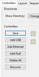
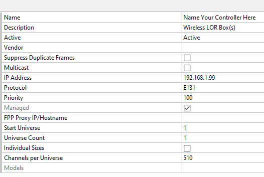
To create a connection to your controller in xLights, you will go to the “Controllers” tab and select “Add Ethernet”
In the newly created controller line item, fill out the necessary information for your LOR controller the way you would with any other new controller:
- Add a unique name
- Give a description so you know what this controller is
- Add the IP Address that was established in the previous step. It is recommended that you have static IPs, but this will also work with Multicast if you prefer (Check the Multicast box above the IP Address line)
- Enter the start universe number. If this is the only thing on your network, you would select 1. If other items are on the network then you would want to select a unique Universe number
- Channels per universe would be 16 if you are only using this to control one LOR board. If you are going to daisy-chain boards, you would use 16x the number of controllers attached (32 for 2 LOR boards, etc)
You can now add elements to your display in xLights and sequence them. Happy Lighting! Contact us with any questions.