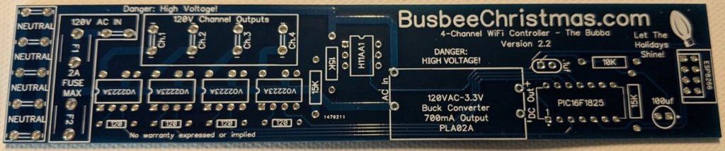
Our Complete 4-Channel AC Controller Kit allows you to build your very own low-cost wireless AC controller. The kit comes with everything you need for the build. Use the steps and images below to help you in your construction.
The blank board that is shipped with your kit will come with all of the necessary markings for components. We have this quick guide to help you assemble the board in a way that enables easy soldering of parts.
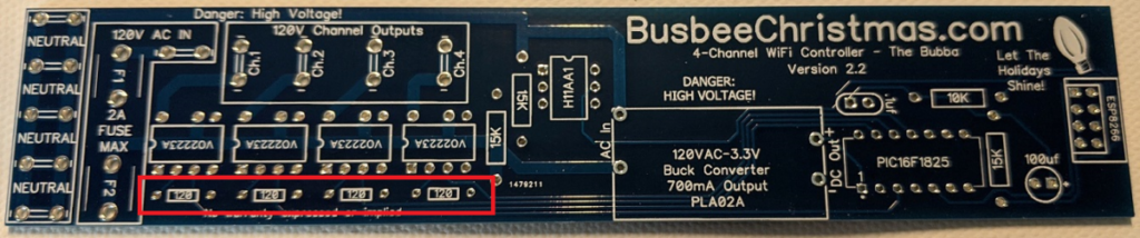
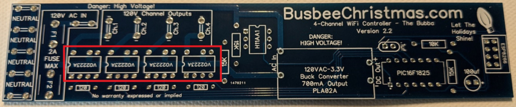
1/ Install the four 120-ohm resistors in the locations shown below:
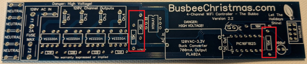
2. Install the three 15k-ohm resistors in the locations shown below:
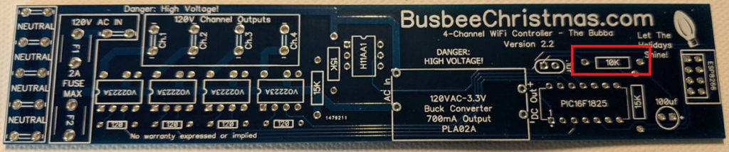
3. Install the single 10k-ohm resistor in the location shown below:
4. Install the four 8-pin sockets in the location below. Note the screen printing for alignment. The chips only have 7 pins, so you will need to remove one pin from the socket in order to fit in the board.
5. Install the 6-pin socket in the location shown below. Note the screen printing for alignment:
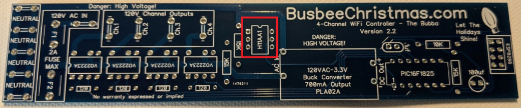
6. Install the 14-pin socket in the location shown below. Note the screen printing for alignment:
7. Install the 8-pin header socket in the location shown below:
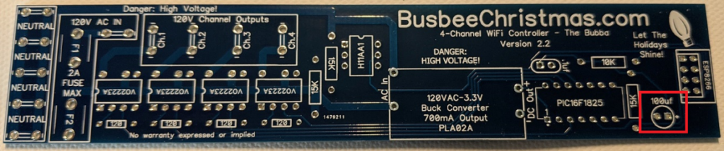
8. Install the 100uf capacitor. Note the orientation of the component. The negative is marked on the side of the capacitor, and the screen printing shows where the positive lead goes:
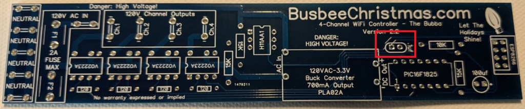
9. Install .1uf capacitor in the location shown below. Orientation does not matter for this component.
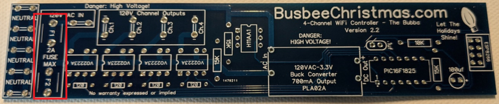
10. Install the two fuse clips. Note the crimp in one end. That should be on the outside so that the fuse fits snugly inside.
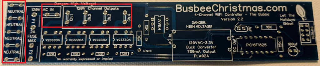
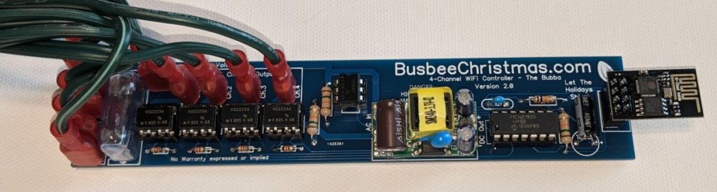
11. Install the 10 spade connectors in the locations shown below. If you plan to solder your wires directly to the board you can skip this step.
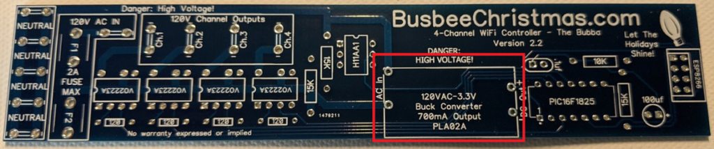
12. Install the PLA02A buck converter in the location shown below. It will only go in one direction based on the pins, so be sure to line up correctly.
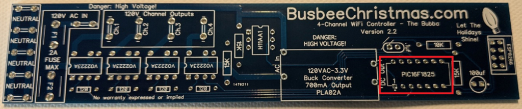
13. Install all of the chips into their respective connectors being sure to note which way pin 1 aligns based on the screen print
14. Install fuse and place the vinyl cover on top to protect the glass fuse.
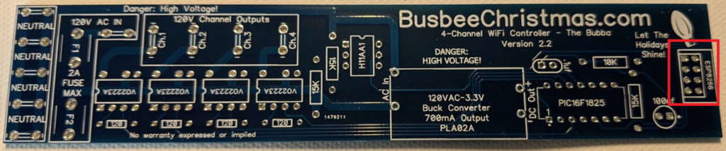
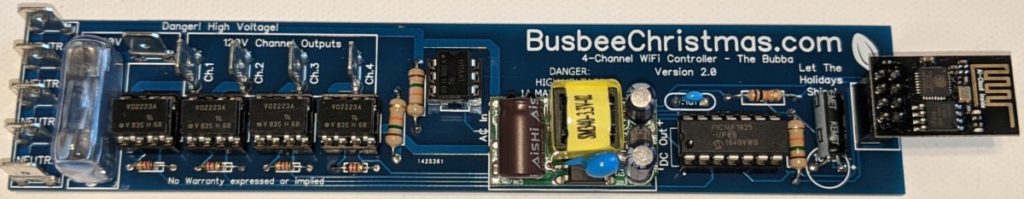
15. Install esp module facing away from board as shown in the image below. You should now have a fully assembled 4- channel wireless controller.
16. Inspect all of your solder joints for good quality connections and look for any possible solder bridges that short pins together. Once you are good with the setup, you are ready to connect it to power.
You are about to connect live power to the board. From this point on you should place the board in a protective cover for your safety. I use a 1-foot long, 2-inch PVC tube and cap to house mine with the power cables hanging out the open end.
17. When it is safe to do so, apply power to the board by connecting to the 120V AC in and a neutral connection.
You will see the LED on the ESP chip light up indicating that it has power. At this point you can wait a minute or so for it to create an access point for you to connect to.
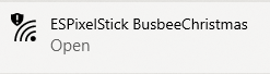
We now need to connect to the 4-Channel AC Controller to set it up on your network. In your device of choice, open your WIFI connections and search for a new open network that begins with “ESPixelStick…” Connect to that network and open a web browser. You may get a notification that there is no internet connection present, so just disregard.
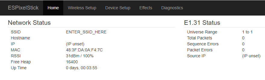
Navigate in your browser to 192.168.4.1 to get to the main menu on the 4-Channel AC Controller. This will give you general information about the board based on the ESPixelStick firmware.
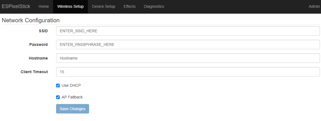
Click on “Wireless Setup” to enter the WiFi settings for your wireless network. Case is important, so be sure the SSID and Password cases match.
- Enter your WiFi SSID (Case sensitive)
- Enter your WiFi password
- Give a hostname so you can easily identify it on your network
- Leave DHCP to let your router assign an IP or uncheck to enter your own IP information
- Leave AP Fallback checked until you confirm that you can get on your WiFi network. Once you go live, you will want to uncheck this. While it is checked you can always connect to the device as shown above.
Click “Save Changes” to save the new configurations
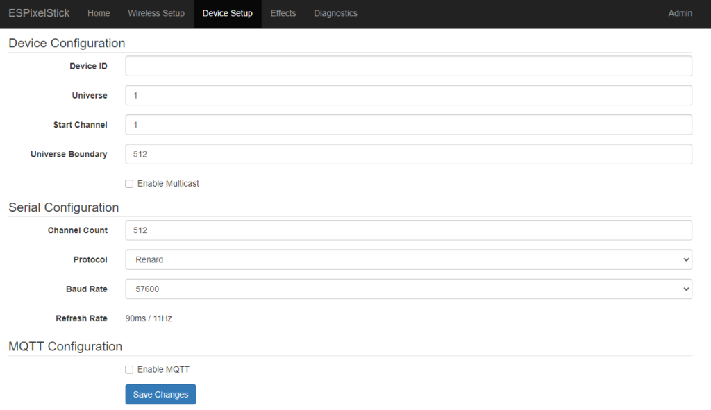
Once the new settings take effect, browse to the new IP that you gave in the last step, or go to your router to see the assigned IP. Put that in the address bar and then select “Device Setup” You will see that the default setting is for Universe 1 with 512 channels. You can change the Universe to match the universe for this controller in xLights (more details on this below).
The board runs on renard firmware, so in the “Device Setup” section you will need to change the protocol to Renard and the baud rate to 57600 if it is not there already.
To check that your board is working properly, connect a string of lights to one of the outlets and browse to the “Effects” tab. Change the color to white and select solid from the effect dropdown. You should now see the lights turn on. If you do not, go back through the configuration to confirm that you have your setup correct.
To create a connection to your controller in xLights, you will go to the “Controllers” tab and select “Add Ethernet”
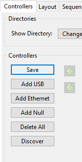
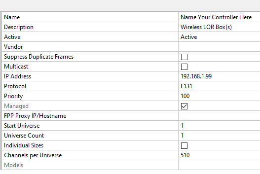
In the newly created controller line item, fill out the necessary information for your LOR controller the way you would with any other new controller:
- Add a unique name
- Give a description so you know what this controller is
- Add the IP Address that was established in the previous step. It is recommended that you have static IPs, but this will also work with Multicast if you prefer (Check the Multicast box above the IP Address line)
- Enter the start universe number. If this is the only thing on your network, you would select 1. If other items are on the network then you would want to select a unique Universe number
- Channels per universe would be 16 if you are only using this to control one LOR board. If you are going to daisy-chain boards, you would use 16x the number of controllers attached (32 for 2 LOR boards, etc)
You can now add elements to your display in xLights and sequence them. Happy Lighting! Contact us with any questions.